Blade Stress Sources
The main stress sources in the HPT blades are the following:
- The centrifugal load, which acts at any section of the airfoil or shank and is produced by the inertia.
- The gas bending moment, which is produced by the momentum and pressure change of the fluid as it passes across the blade.
- The bending moment, which is derived from the centrifugal load that acts at a point that does not lie radially above the centroid of the root section (or any other reference section).
- The shear load, which arises from the gas pressure or from the centrifugal untwisting of the blade.
- The load that is caused due to thermal gradients.
Disc Stress Sources
The most significant stress sources in the HPT discs are the following:
- The centrifugal body force of disc, which is caused due to the rotary inertia field.
- The radial centrifugal load, which is produced by the “dead” mass of the blades, shrouds, etc and acts on the circumference of the disc like a “rim stress”.
- The temperature gradient between the bore and the rim of the disc, in combination with the coefficient of thermal expansion, produces a thermal stress.
- The torque load, which produces shear stresses in the body of the disc. This occurs either by steady-state torque transmission from the turbine to compressor or by the inertia loading creation as the machine speeds up or slows down.
- The bending loads, which act on the disc due to the pressure difference across the stage or due to the gas bending loads on the blades.
Cooling Section
- It must have a high melting point.
- It should be resistant to oxidation.
- It must have high-temperature strength and microstructure stability.
- It should have low density and high stiffness.
- It must be easily fabricated and with low cost.
- It should have reproducible performances.
The most common materials that meet the above requirements are nickel-based alloys.
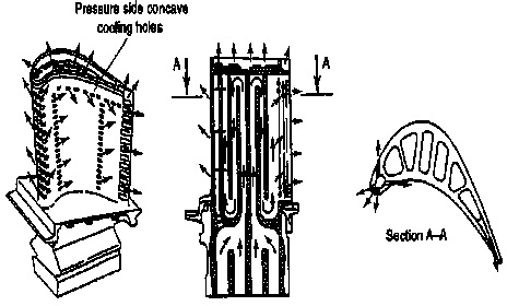
Cooling systems for gas turbine engines are constituted of a number of air flow paths, which are parallel to the main gas path. The air that flows within these paths is extracted from the compressor either by slots in the outer casing or by gaps and holes in the drum. The air then is transferred either internally through orifices and labyrinths, or externally by pipes outside of the engine casing. If the air is extracted earlier from the compressor, the performance loss will be lower, due to the less work that has been given to air by the compressor.
Thermal Barrier Coating
- If the coated blades continue to work at the same external temperature, either their lifetime will increase (because the temperature of the blades will be reduced), or the cooling air flow will be reduced.
- If the coated blades work at higher external temperatures the turbine efficiency will increase.
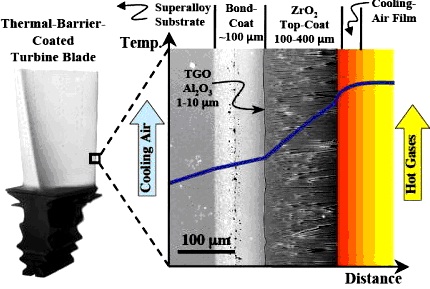
The advantages that can be achieved with the use of thermal barrier coatings are the following:
- Lower blade metal temperature.
- Lower transient thermal stress.
- Higher operating temperature and particularly, higher turbine entry temperature (TET), which leads to a higher efficiency.
- Reduction in the air flow that is required for cooling.
- Improved resistance to corrosion.
References
Read also

Thank you very much for your comment my friend. It is always nice to see your opinion about the stuff presented here.
By the way, I saw a lot of useful equipment on your site.
Centrifugal compressor
Thank you
The information you shared is very informative.